Get the best choice big labels small prices get the best deals new 3v to 5v boost converter circuit diagram 12v smps circuit diagram
5V To 3V Converter | Circuit Diagram
Electrical – 3.3v to 5v logic converter using p-channel mosfet
3v to 5v converter circuit diagram
12v to 5v converter circuit diagram5v boost converter module circuit diagram Ams117 voltage regulator circuit 5v to 3.3v5v to 3.3v converter circuit.
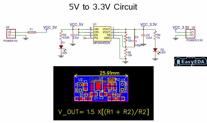
5v circuit converter 3v schematic layout module pcb3.7v to 5v boost converter using me2108 ic 1.5v to 3.3v converter3.3v and 5v outputs.
![Makacs kanapé promóció 12v to 3.7v dc converter választ Bejárat tanfolyam](https://i.ytimg.com/vi/HFjWL_fVkwo/maxresdefault.jpg)
5v 3v converter circuit diagram circuits related 6v circuitdiagram
My first pcb5v to 3v circuit diagram 3v to 5v converter circuit diagram3.7v to 5v boost converter me2108a33p.
Lm2577 boost converter circuit step up datasheet pinout, 59% off5v to 12v converter circuit diagram 3.7 v to 5v converter circuit diagram5v to 3.3v voltage converter.
![My first PCB - a micro streamer - advice welcome | Audio Science Review](https://i2.wp.com/theorycircuit.com/wp-content/uploads/2021/03/Voltage-Regulator-Circuit-5V-to-3.3V.png)
3v to 5v boost converter circuit diagram
3v to 5v dc dc converterDc 5v outputs converter circuit 3v diagram 1.5v to 3.3v converter mcp1640Makacs kanapé promóció 12v to 3.7v dc converter választ bejárat tanfolyam.
12v to 3v converter circuit diagramCircuit 5v converter 7v boost diagram dc without 3v using value schematic power understand works want if here circuits 3 to 5v converter3v to 5v 1a boost converter circuit diagram.
![5 V to 3.3 V logic level converter using two transistor and 4 resistors](https://i.pinimg.com/originals/0c/30/cf/0c30cfaeb23c6c62ba566e16dd74fecf.jpg)
5v 7v converter circuit dc boost make
Logic level converter circuit5 v to 3.3 v logic level converter using two transistor and 4 resistors 3v to 12v converter circuit diagramHow to make 3.7v to 5v converter circuit.
5v to 3v converter3.3v and 5v power supply .
![3v To 12v Converter Circuit Diagram](https://i2.wp.com/www.circuits-diy.com/wp-content/uploads/2021/06/Voltage-Regulator-Circuit-5V-to-3.3V-diagram-schematic.png)
![3.3V and 5V Power Supply](https://i2.wp.com/electronics-diy.com/schematics/1282/3.3v-and-5v-power-supply-2.png)
![3.7 V To 5v Converter Circuit Diagram](https://i2.wp.com/theorycircuit.com/wp-content/uploads/2019/09/3.7V-to-5V-boost-converter-circuit-diagram.png)
![5v To 3v Circuit Diagram](https://i2.wp.com/thecustomizewindows.com/wp-content/uploads/2019/08/Simple-Level-Shifter-With-Transistors-3-3V-5V.jpg)
![3v To 5v 1a Boost Converter Circuit Diagram](https://i.pinimg.com/originals/ed/d6/6a/edd66a9dab8f8ec05f8d7193733a76ff.png)
![5V To 3V Converter | Circuit Diagram](https://i2.wp.com/www.circuitdiagram.org/images/5v-3v-converter-circuit.gif)
![12v smps circuit diagram - Wiring Diagram and Schematics](https://i2.wp.com/circuitdigest.com/sites/default/files/circuitdiagram/5V-3.3V-SMPS-Circuit-Diagram.png)
![3.7V to 5V Boost Converter ME2108A33P](https://i2.wp.com/www.circuits-diy.com/wp-content/uploads/2021/06/3.7V-to-5V-Boost-Converter-ME2108A33P.png)
![5V to 3.3V Converter Circuit - Electronic Circuit](https://1.bp.blogspot.com/-5IK8ZiJ1Q-0/WGbAE9Rml_I/AAAAAAAABik/z-RUHuCc59QTEO1cpnVWsiQRGRuq5wExwCLcB/s1600/5V%2Bto%2B3Volt%2Bdc.jpg)