Circuit translation: 16 by 4 bit memory 16*4 bit ram from 4*4 ram. Memory interface 8086 bit 16 using rams eproms decoders ram separate edurev two eeproms static
logical circuit of 8*4 bit RAM. | Download Scientific Diagram
4-bit shift register
Register bit shift parallel serial diagram bits figure shown input load draw control output solved timing into
The above fig shows the 4-bit r/w memory circuit comprising of fourArithmetic logic decrement increment subtract Ram circuit diagram4-bit computer built on breadboards.
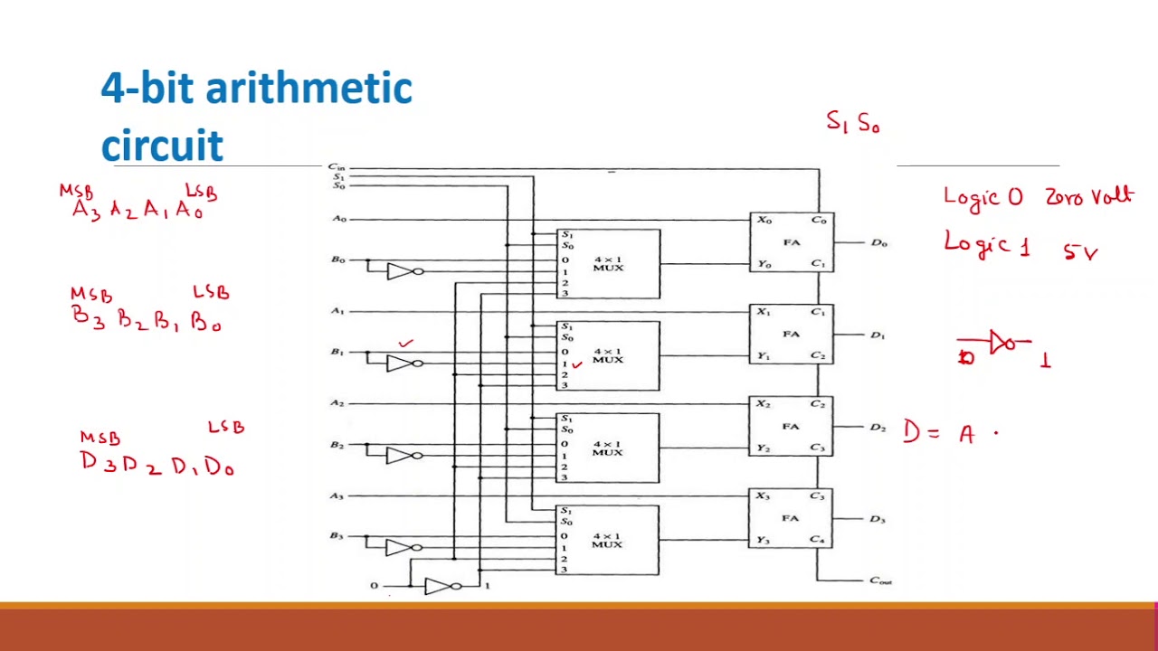
Virtual labsExtend this 4-bit ram (one of two ram locations Electronic – 4×1 bit ram implementation – valuable tech notes18a 4 bit arithmetic circuit.

Bit alu logic diagram
8*4 bit ram from 4*4 bit ram.Logic binary Solved a 4-bit shift register shown in figure 7 is to beRam bit locations four extend two.
Ram memory structure random access basic write ppt read powerpoint presentation chip logic data lines address selectEeweb maxfield ram 4 bit ram circuit diagramRam section circuit diagram.
![[DIAGRAM] Logic Diagram 4 X 3 Memory - MYDIAGRAM.ONLINE](https://i.ytimg.com/vi/6o1-sQRNqcA/maxresdefault.jpg)
Digital logic
Cs 3410 spring 2016 lab 1Memory circuit bit 16 diagram schematic applications entryway products Galactic electronics projectsCs355 sylabus.
Virtual labsRegister bit shift electronics digital Ram memory circuit bit cell binary circuits watson figure latech edu4-bit computer circuit diagram.

Hello, please help me draw this 4*4 bit ram circuit
Ram memory structure access random memoriesBuilding a 4-bit computer from the ground up Cnc axis4 board schematics (rev. a)Cpu bit memory counter register 2114 program static.
Logical circuit of 8*4 bit ram.Bit alu adder circuit diagram signed cs project unsigned complement spring adders use two note both lab cornell courses edu 4*16 bit ram from 4*4 bit ram.Modulo 6 counter jk flip flops.

16*4 bit ram from 4*4 ram.
Ram (random access memory) structure[diagram] logic diagram 4 x 3 memory .
.